Oh no you've got a flat! Good thing you have one of the world's only motorcycle with a built in spare wheel! Here we'll show you how to properly swap out your front wheel. But first, a gentle message from the lawyers:
CAUTION! TO PREVENT AN UNCONTROLLABLE ROLLING HAZARD ALWAYS WORK ON A LEVEL SURFACE. USE CHOCKS, WOOD, ROCKS OR OTHER SUITABLE OBJECT TO PREVENT ROLLING.
ALWAYS USE CAUTION WHEN THE MOTORCYCLE IS ELEVATED AND THE WHEELS ARE REMOVED. WORK TO THE SIDE; NEVER WORK UNDER THE MOTORCYCLE WHILE SUSPENDED BY THE CENTER STAND, HOIST, JACK OR BY ANY OTHER MEANS.
WARNING! MAX SPEED OF THE SPARE WHEEL ASSEMBLY IS 50MPH (80KMH)! THE SPARE WHEEL ASSEMBLY IS FOR TEMPORARY USE ONLY! REPAIR AND REPLACE THE STOCK WHEEL AND RETURN TO THE ORIGINAL POSITION AS SOON AS POSSIBLE!
FRONT SPARE WHEEL INSTALLATION
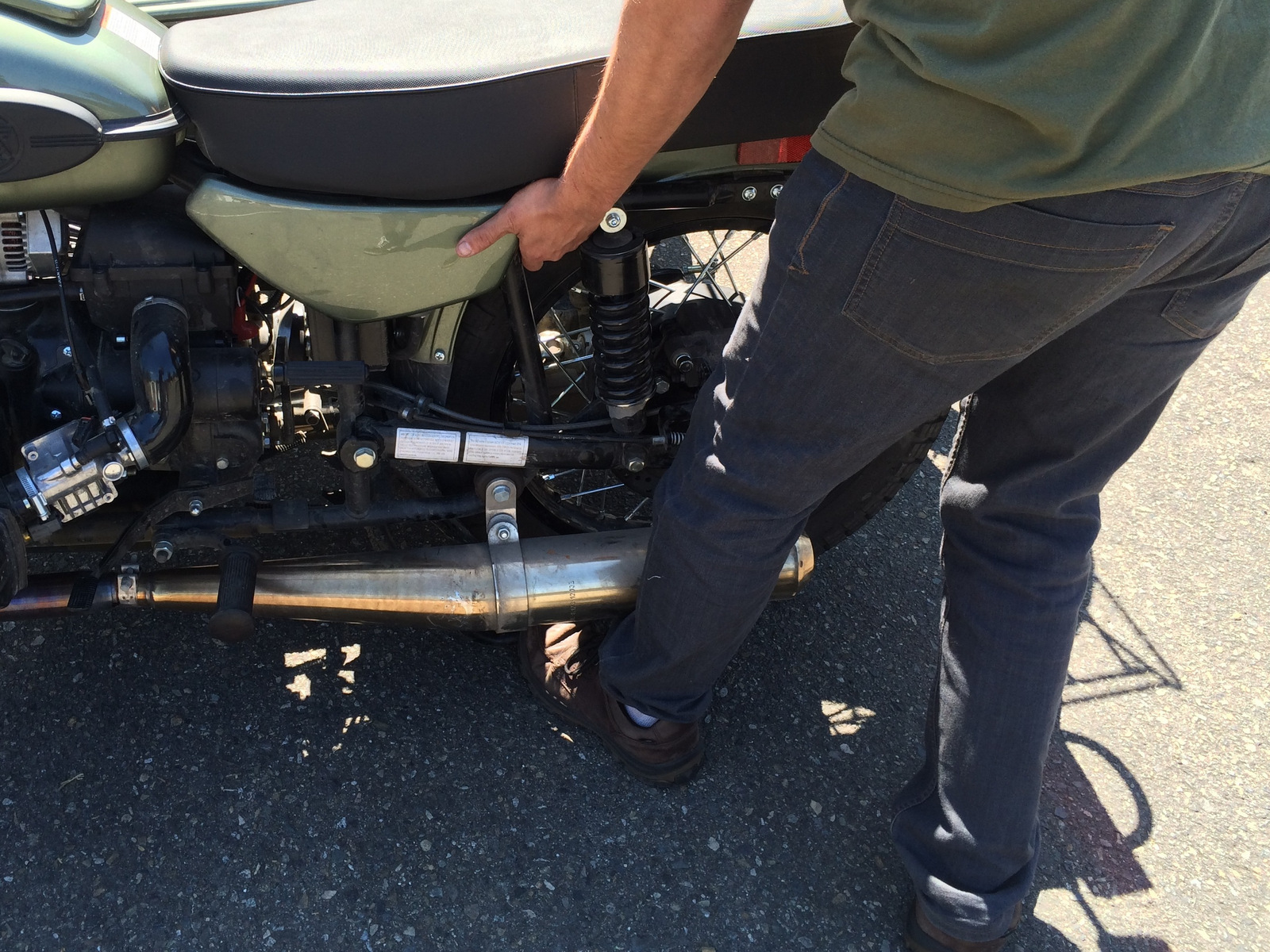
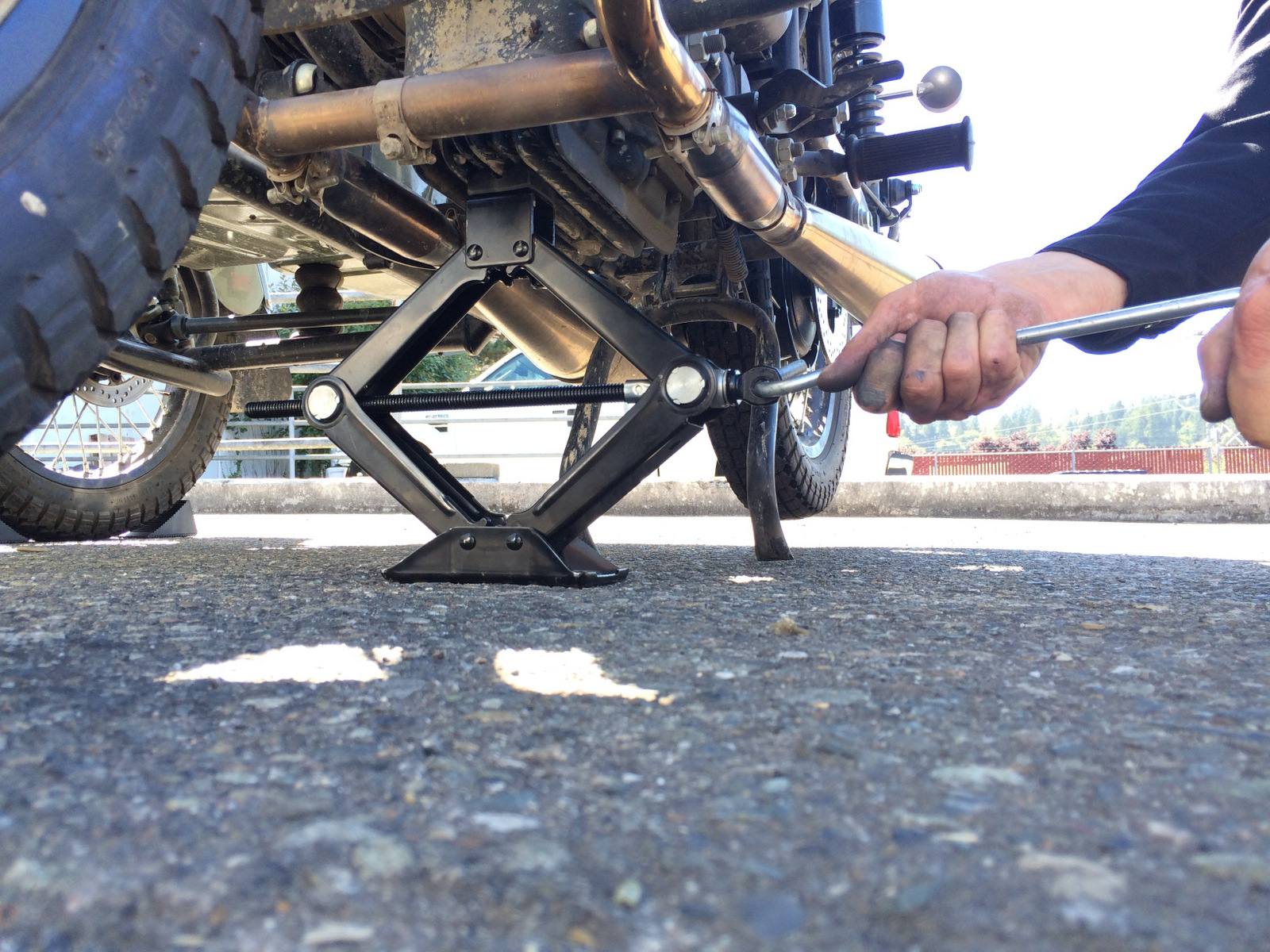
Step 1: Place the motorcycle onto the center stand.
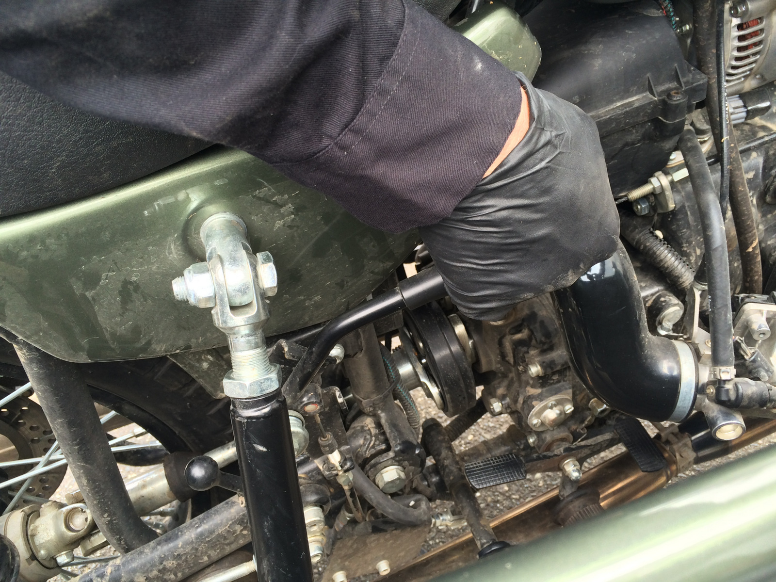
- Use a jack, jack stand or similar method placed under the engines oil sump to suspend the front wheel assembly off the ground.
- If an assistant is available they may be employed to assist with placing a jack stand and stabilizing the motorcycle.
- Applying minimal downward force to the rear fender support easily suspends the front wheel off the ground when the center stand is deployed.
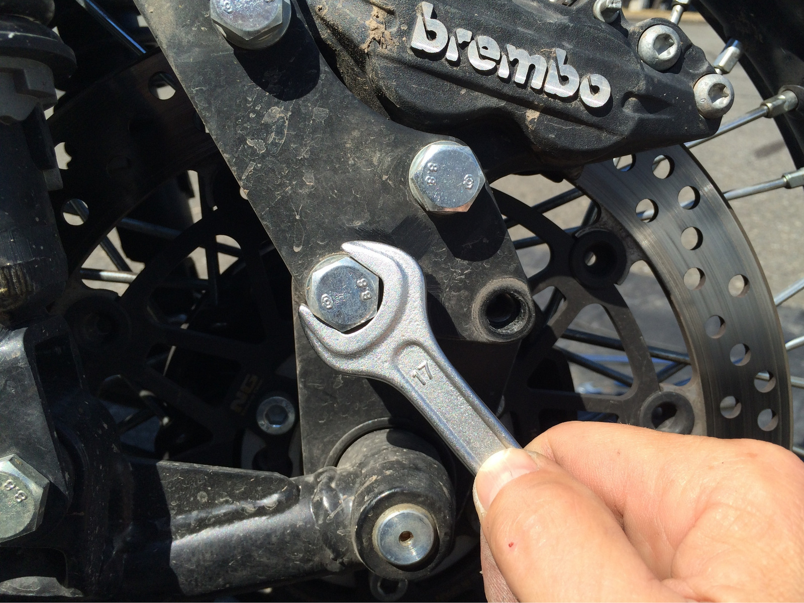
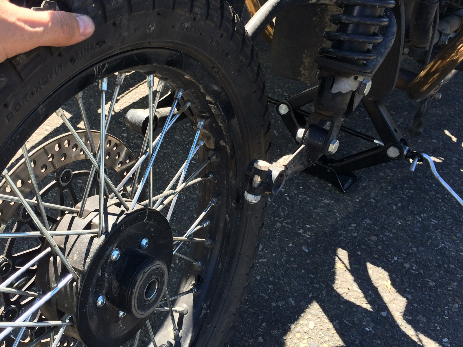
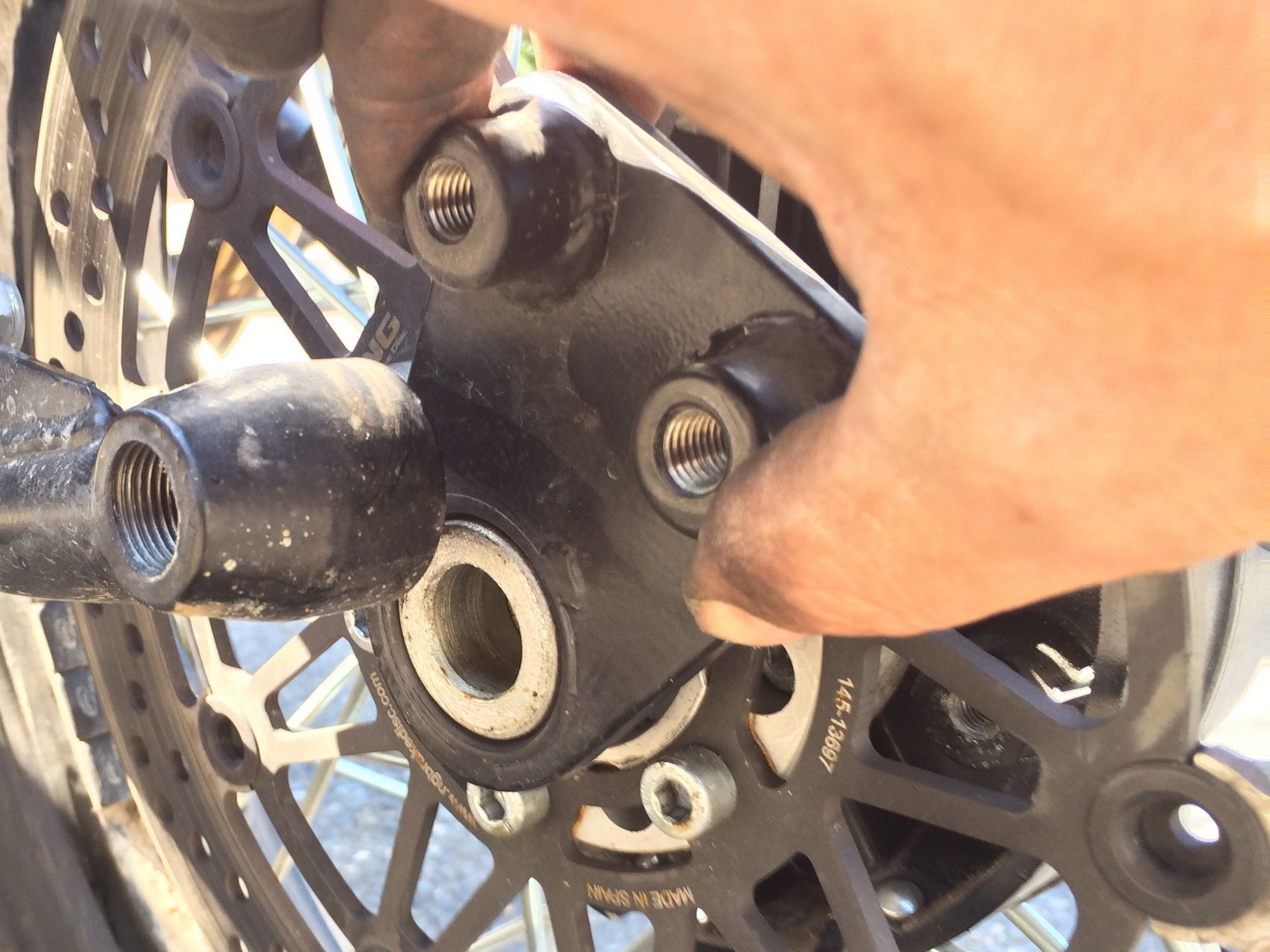
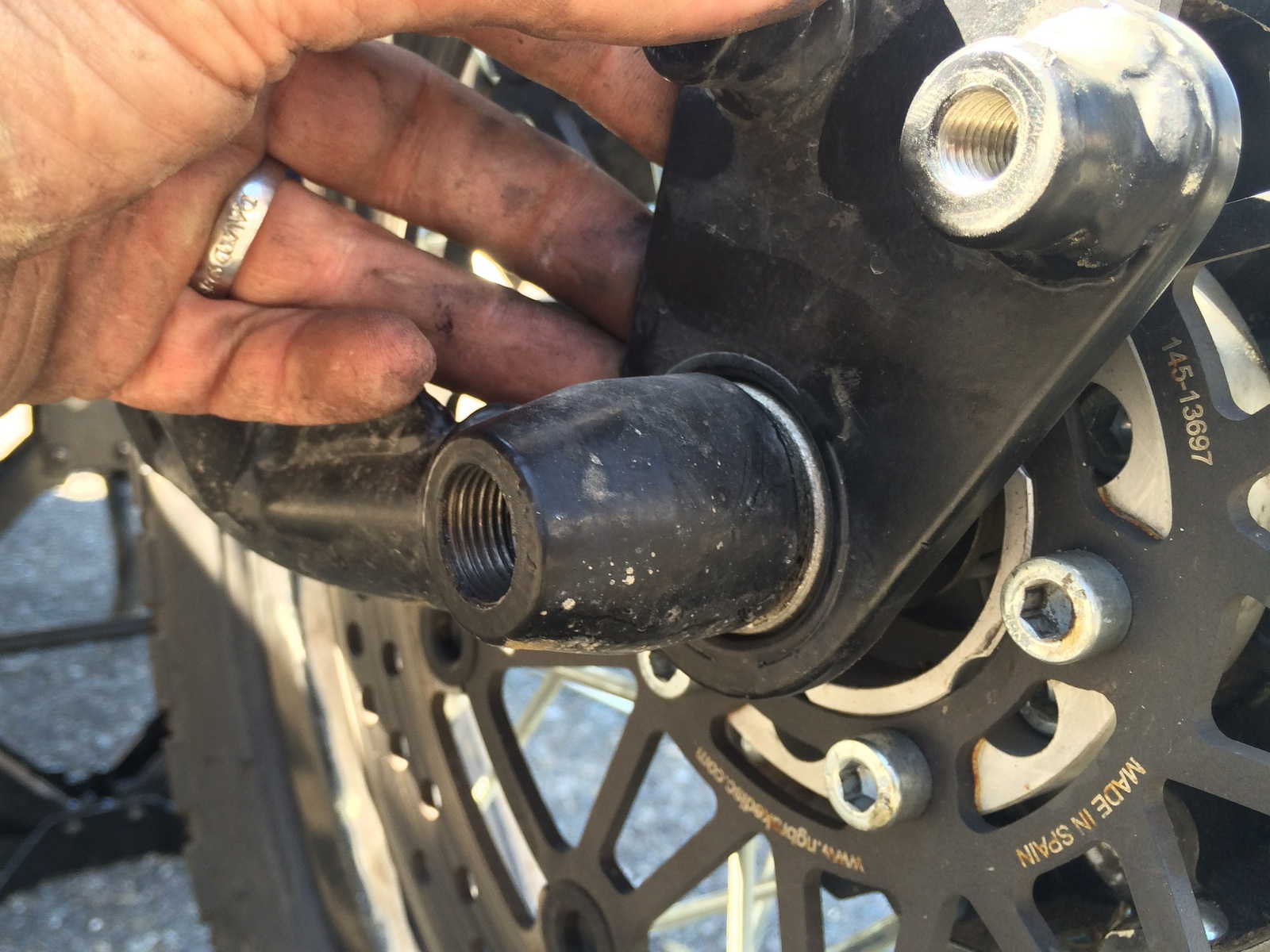
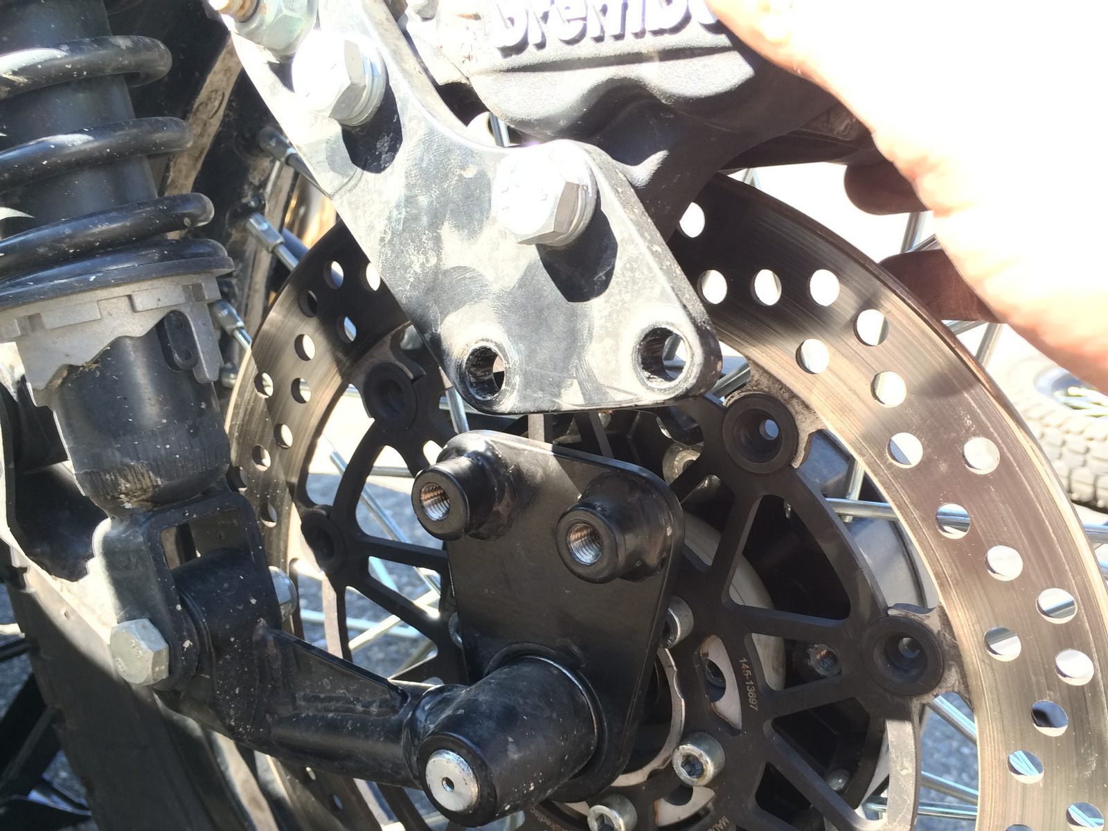
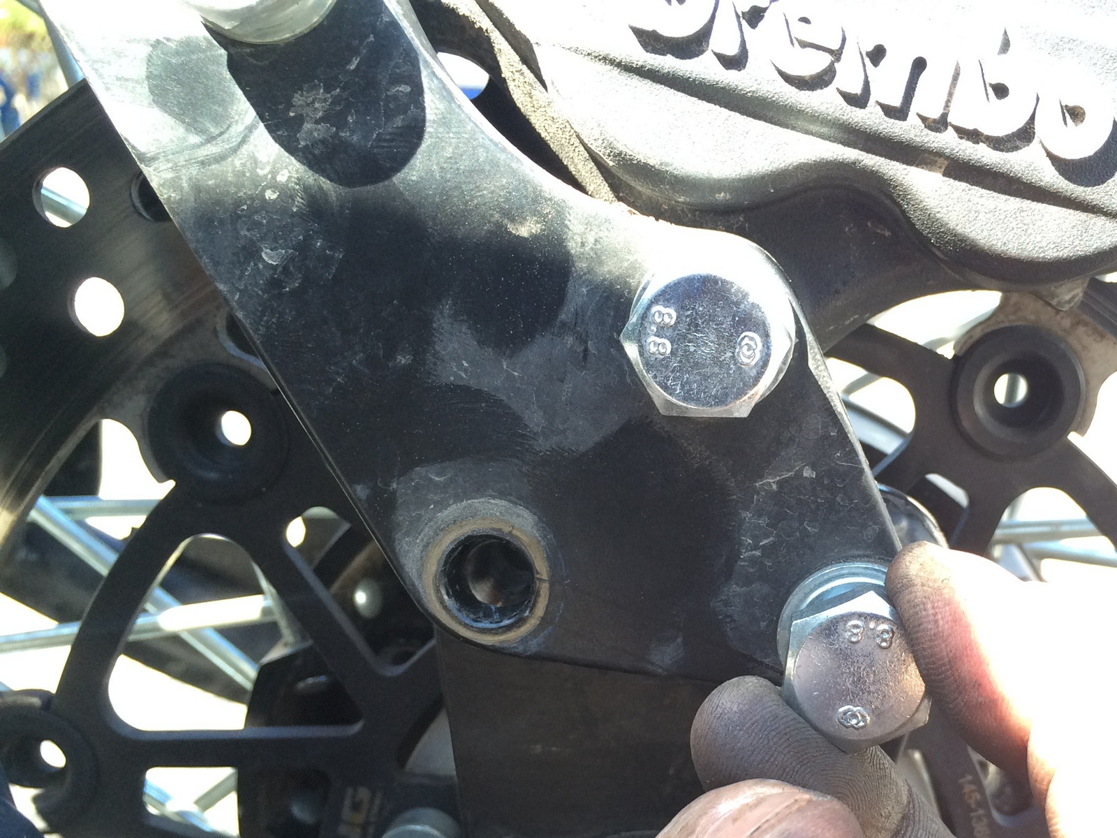
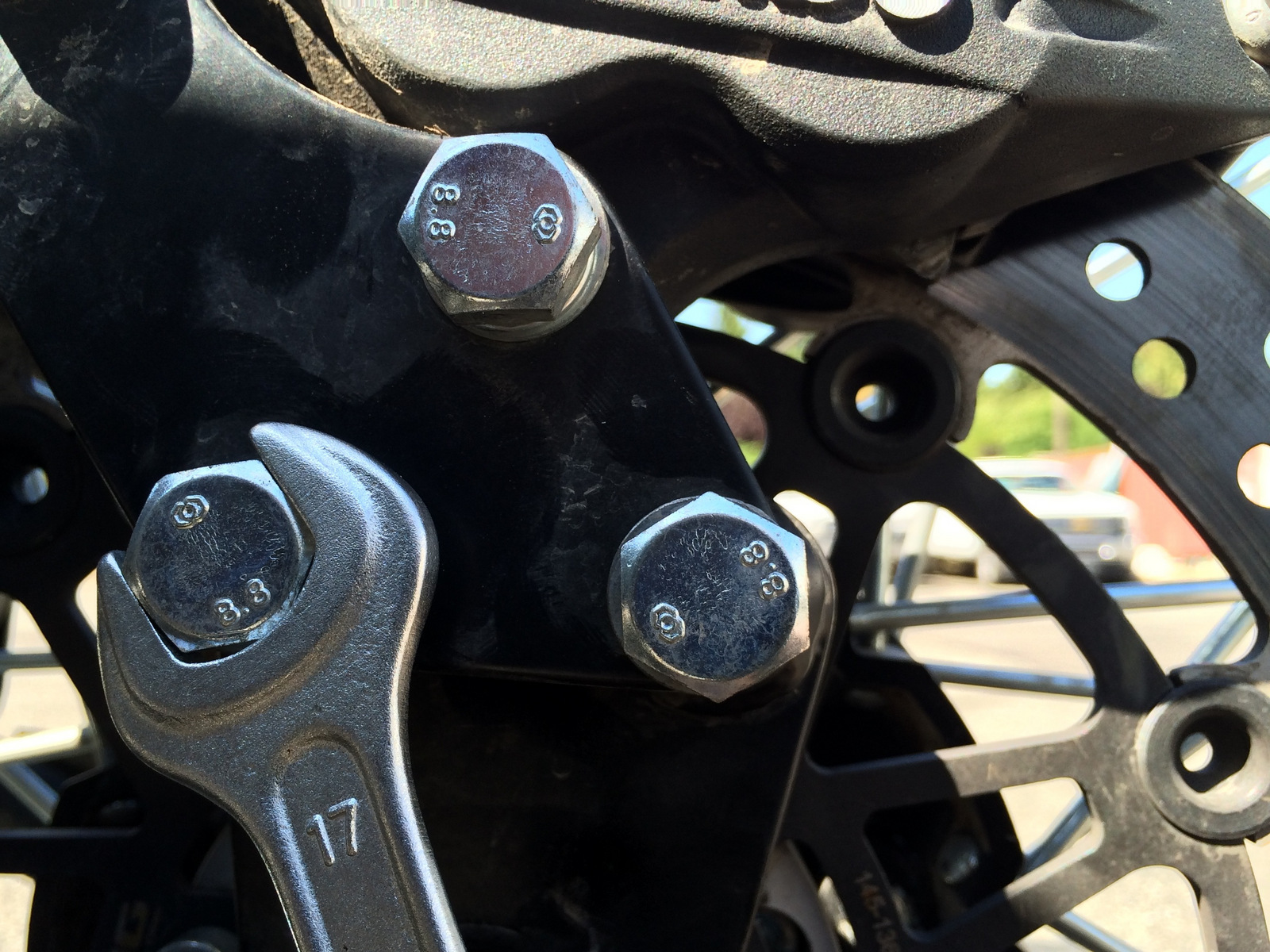
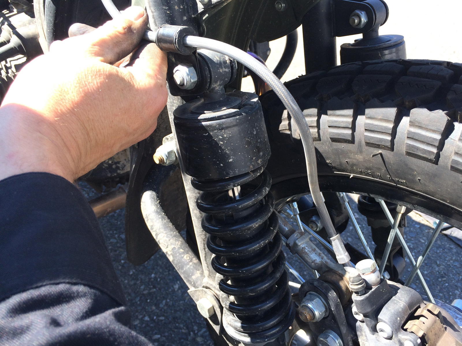
Step 2: Loosen and remove the two bolts securing the front brake caliper upper bracket to the lower caliper bracket with a 17mm tool.
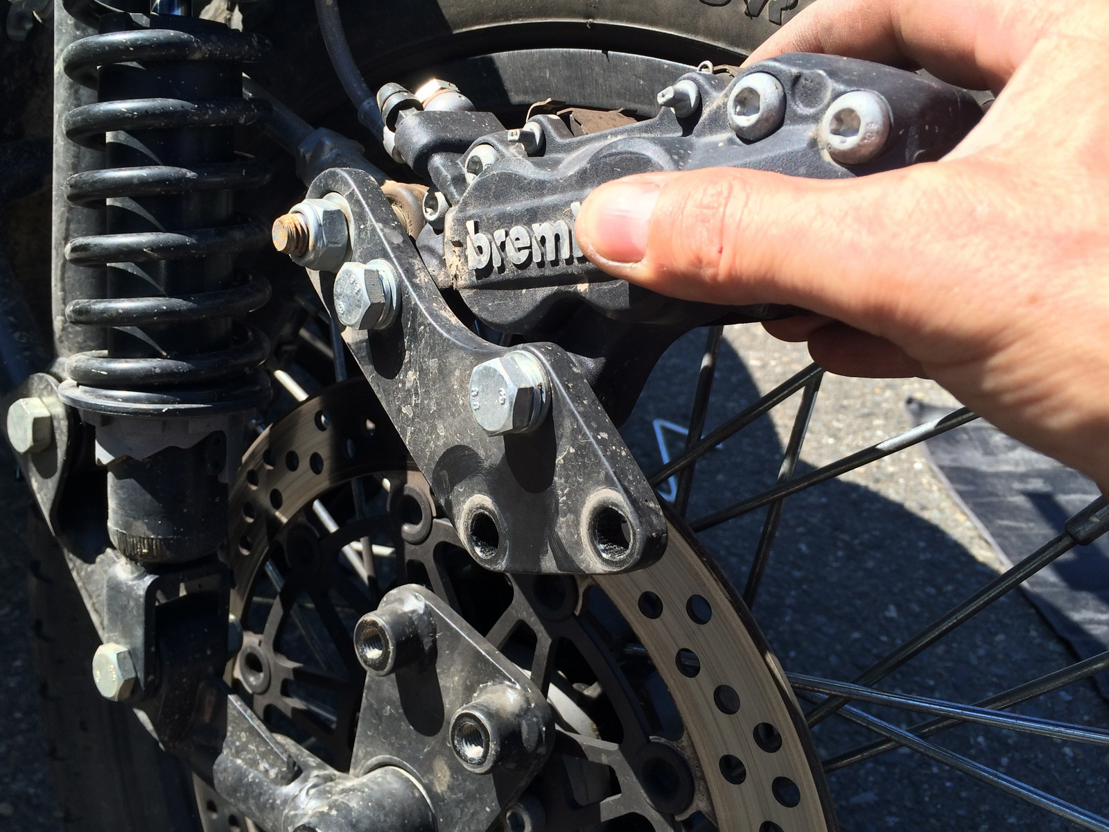
Step 3: Lift the front caliper up off the front rotor and suspend the front caliper from the front fender support with a zip tie, elastic cord or other suitable means.
Note: We have pre-assembled all components and included necessary hardware when required to assure proper alignment between the caliper and rotor.
If shims and/or spacers are present when loosening the front brake caliper from the caliper mounting bracket, the shims and/or spacers will need to be re-installed in the exact same location as they were removed. Take note of shim and/or spacer placement. DO NOT DISCARD!
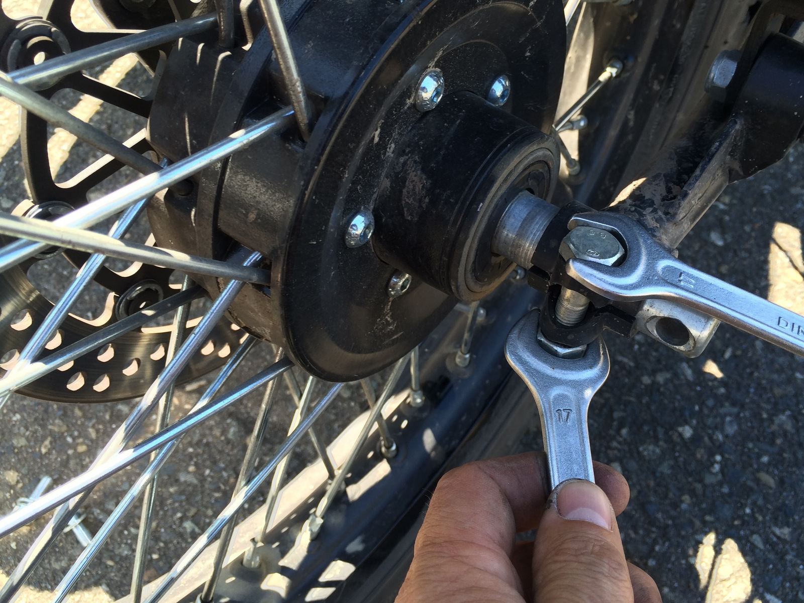
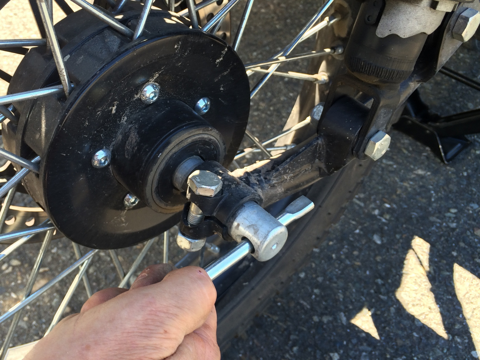
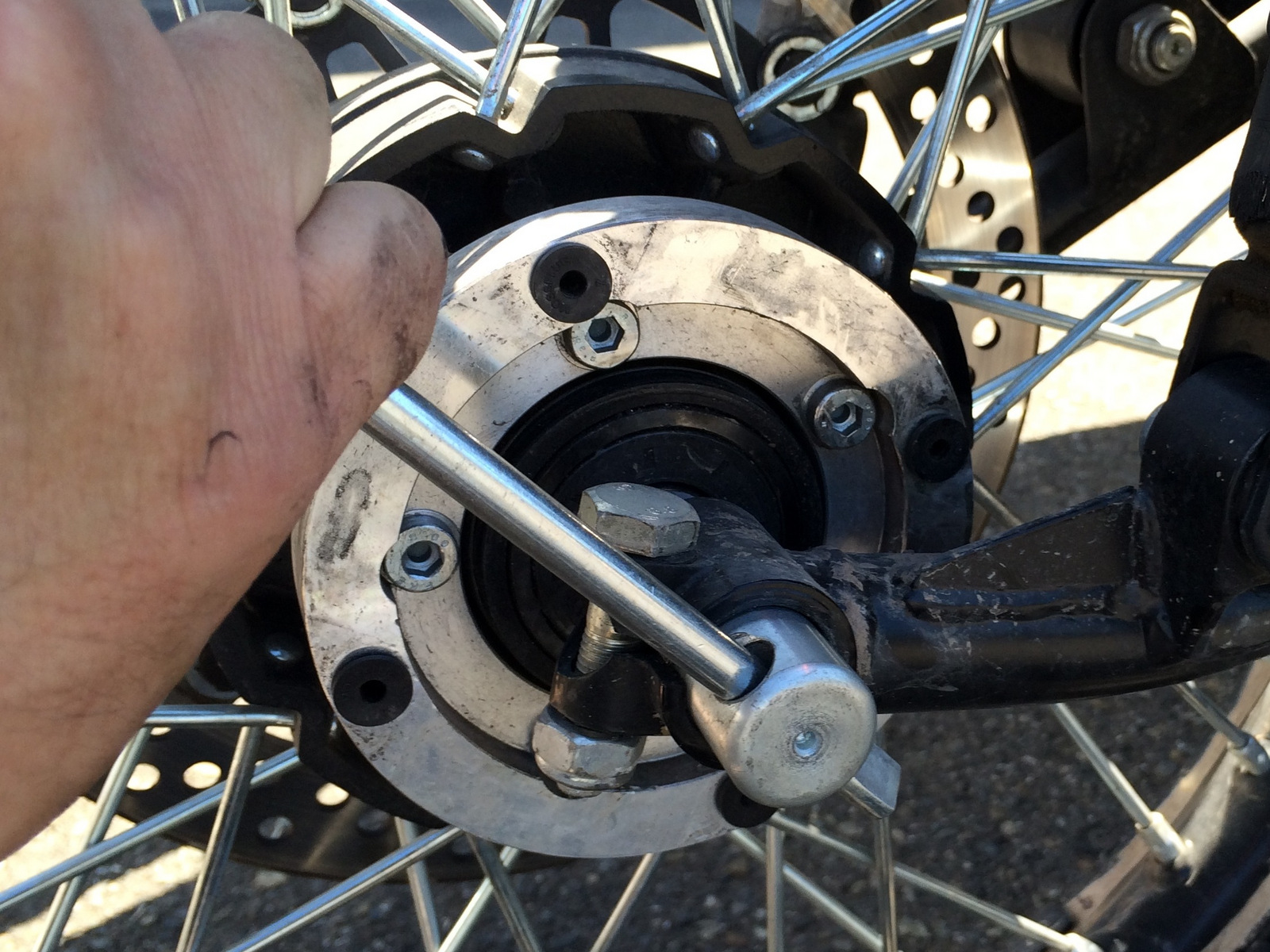
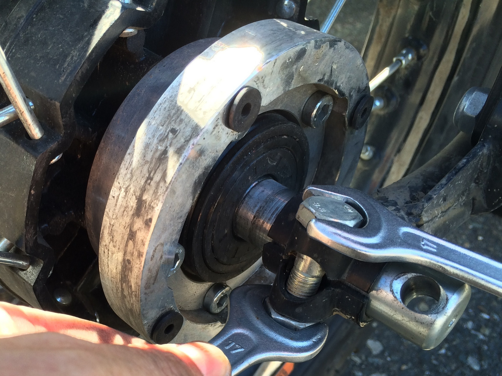
Step 4: Loosen the front axle pinch bolt on the left side of the front swing arm using two (2) 17mm tools.
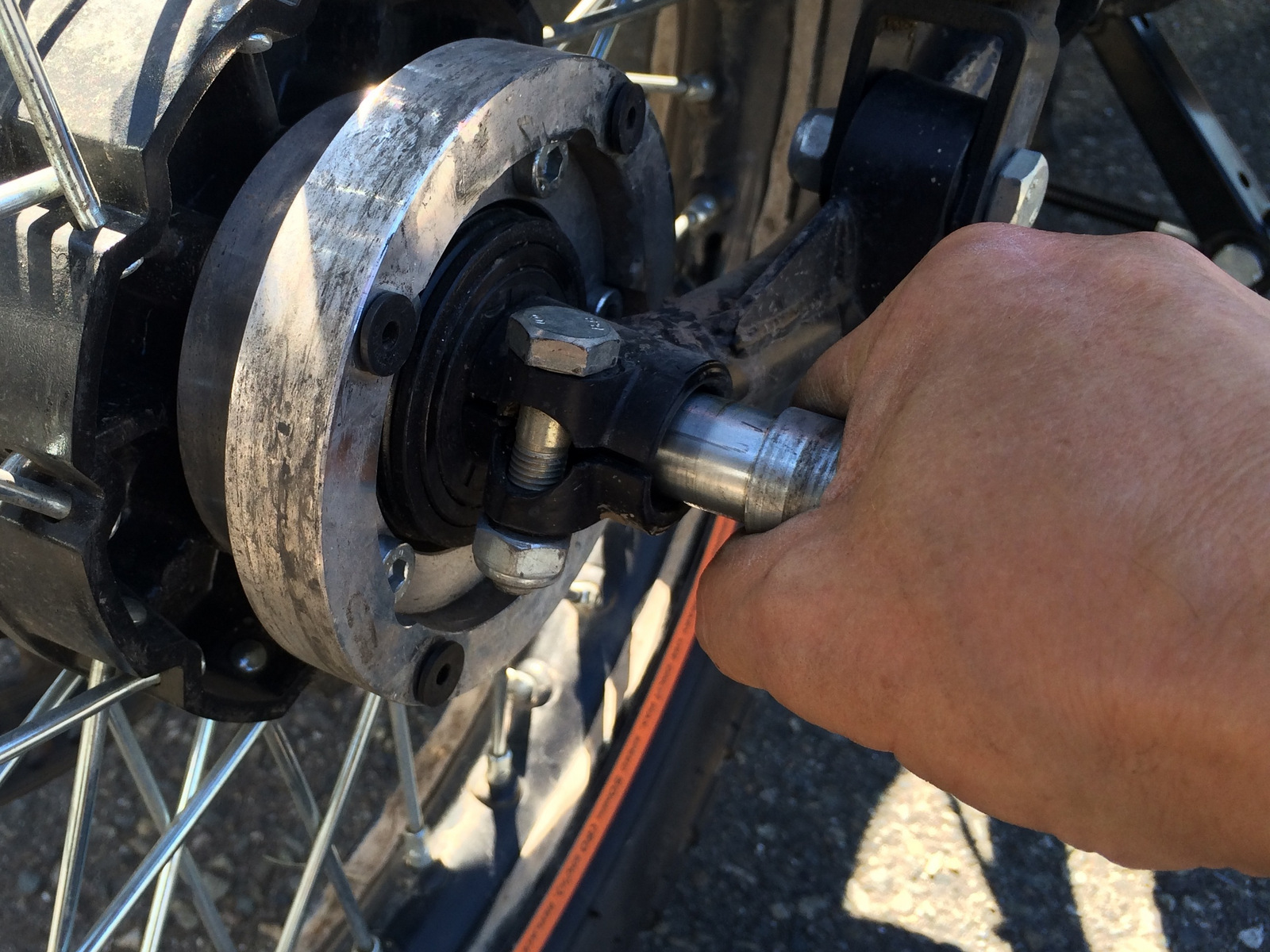
Step 5: Insert a suitable tool (screwdriver works well) into the hole on the left side of the axle and turn clockwise to loosen the axle from the front swing arm.
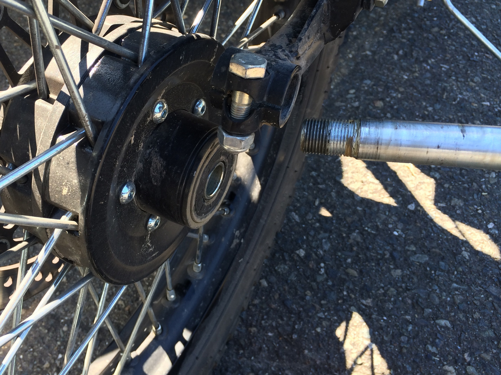
Step 6: Remove the axle.
Step 7: Remove the front wheel assembly.
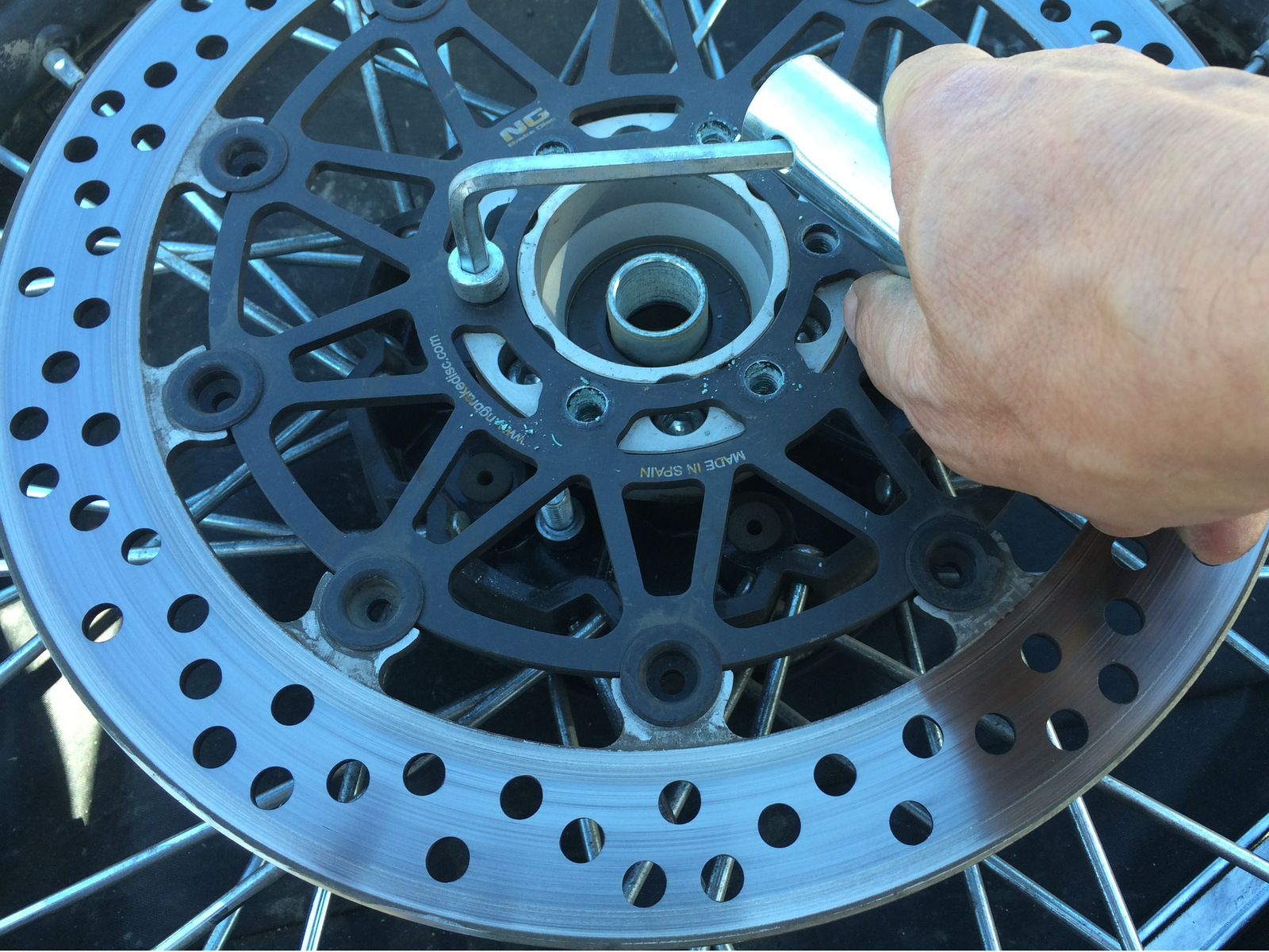
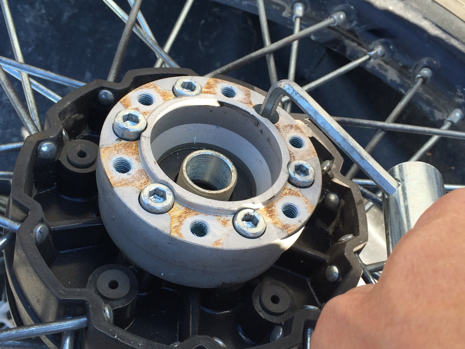
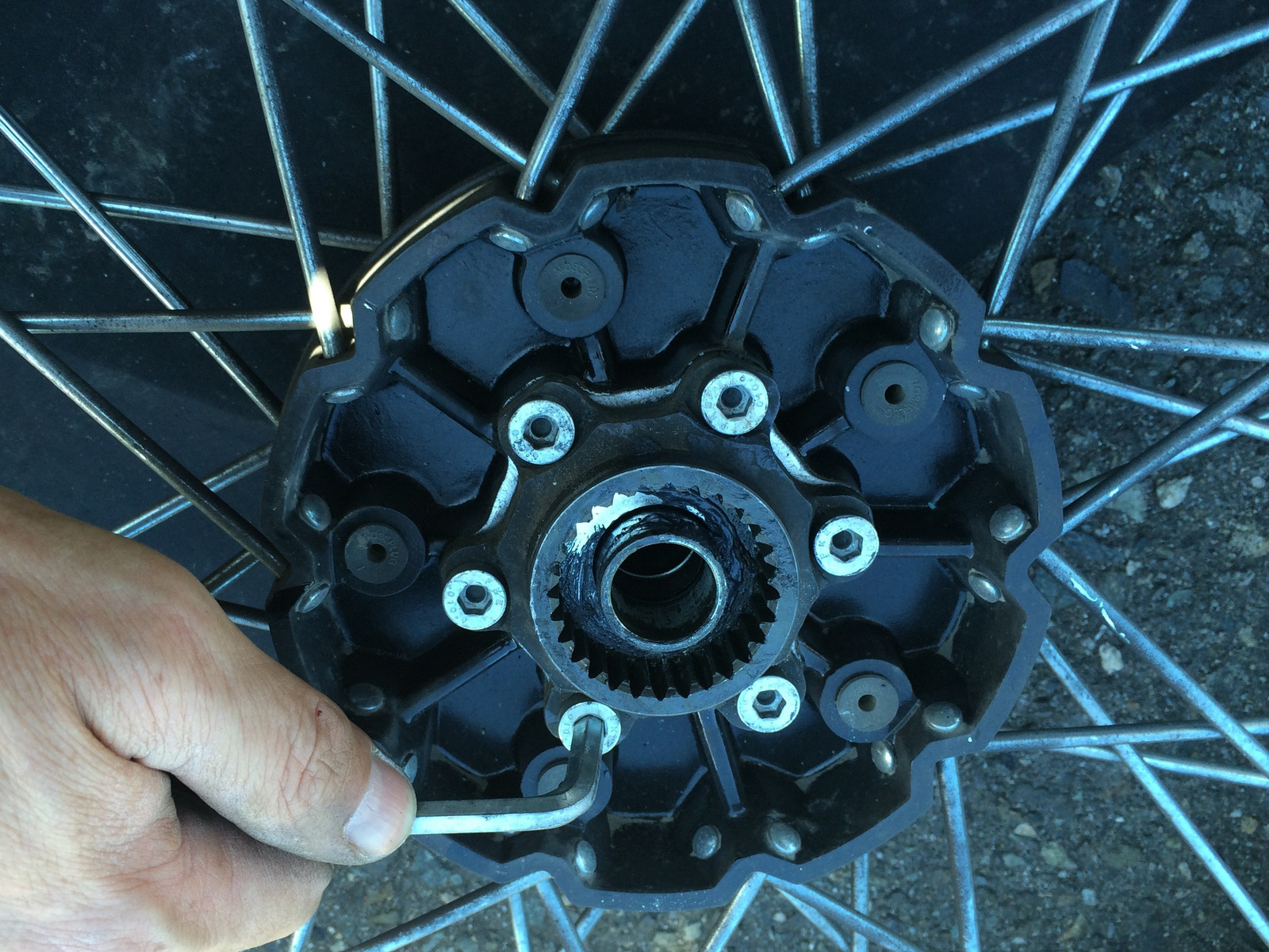
Step 8: Remove the six (6) socket head cap screws retaining the front rotor to the front rotor spacer using a 6mm tool.
Step 9: Remove the six (6) socket head cap screws retaining the front rotor spacer to the front hub.
When the stock front wheel assembly is repaired be sure to tap and clean all threaded mounting holes and hardware threads of old thread locking compound and apply new medium strength thread locking compound on all rotor hardware.
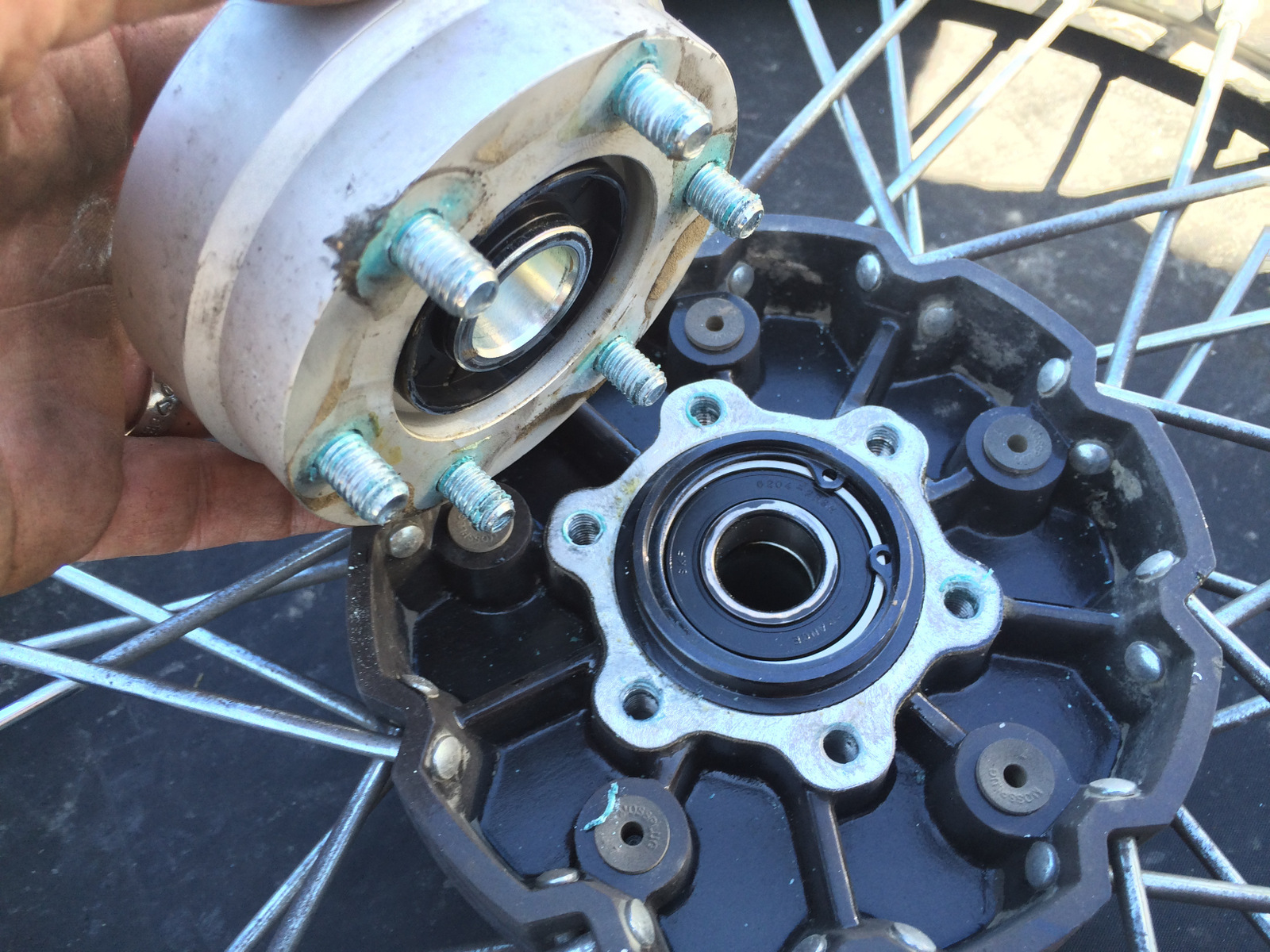
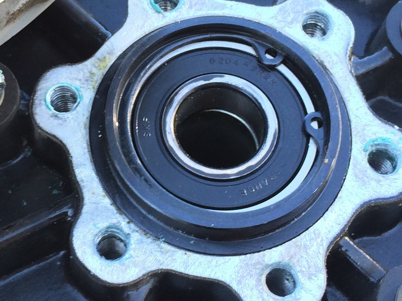
Step 10: Remove the right side front hub retaining circlip using the small screwdriver found in the toolkit or other suitable tool.
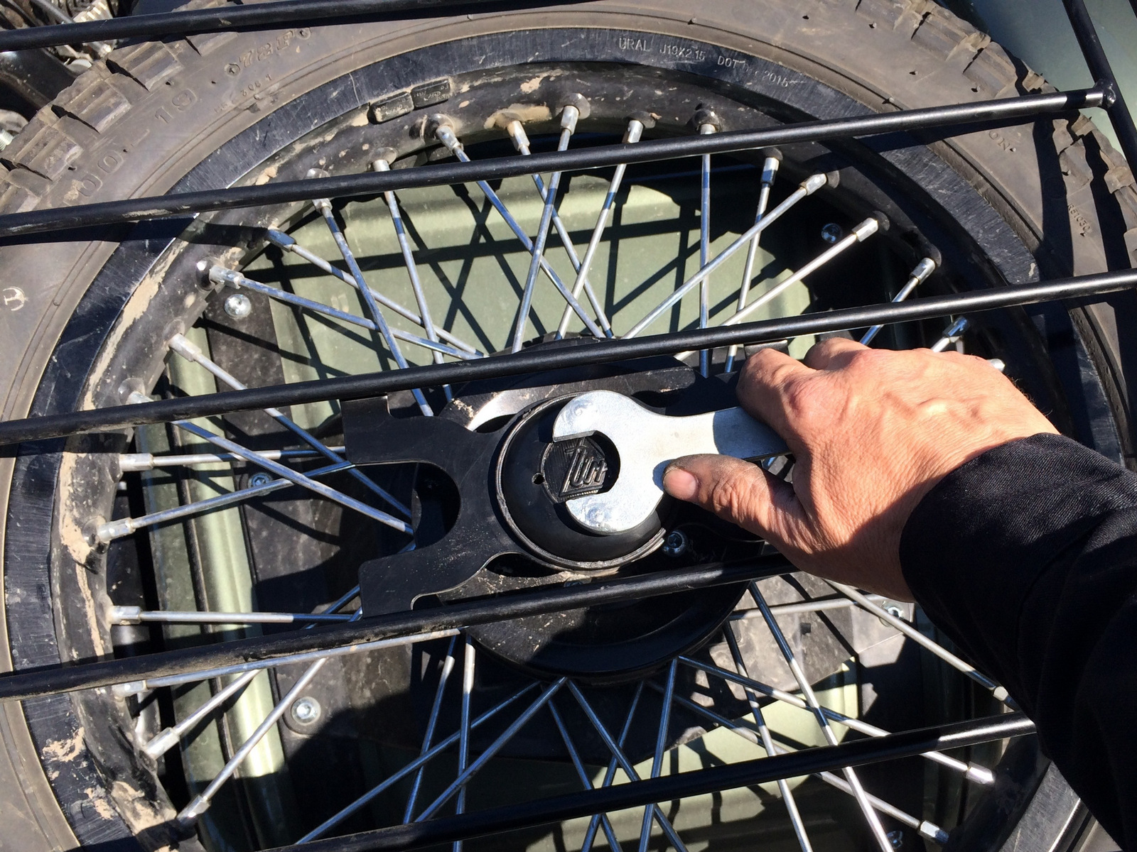
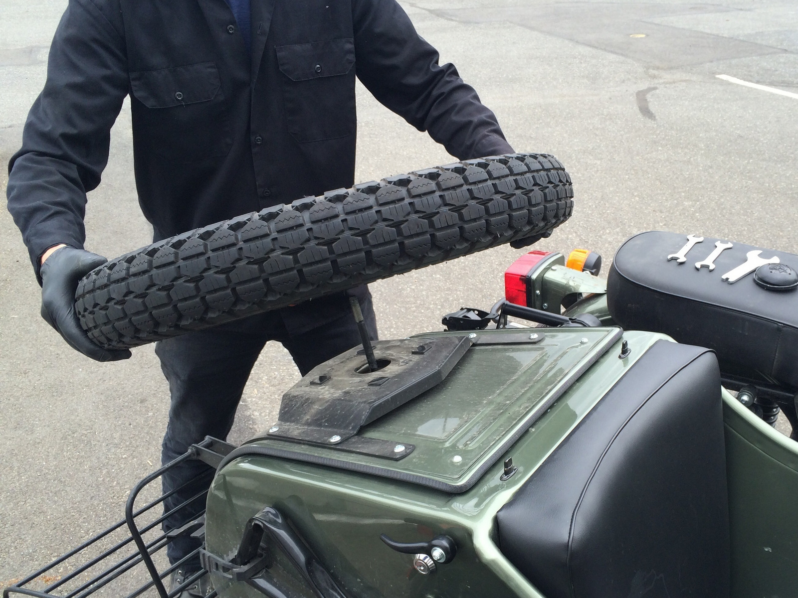
Step 11: Loosen the spare wheel retaining nut using tool from your Ural tool kit and remove the spare from the spare tire.
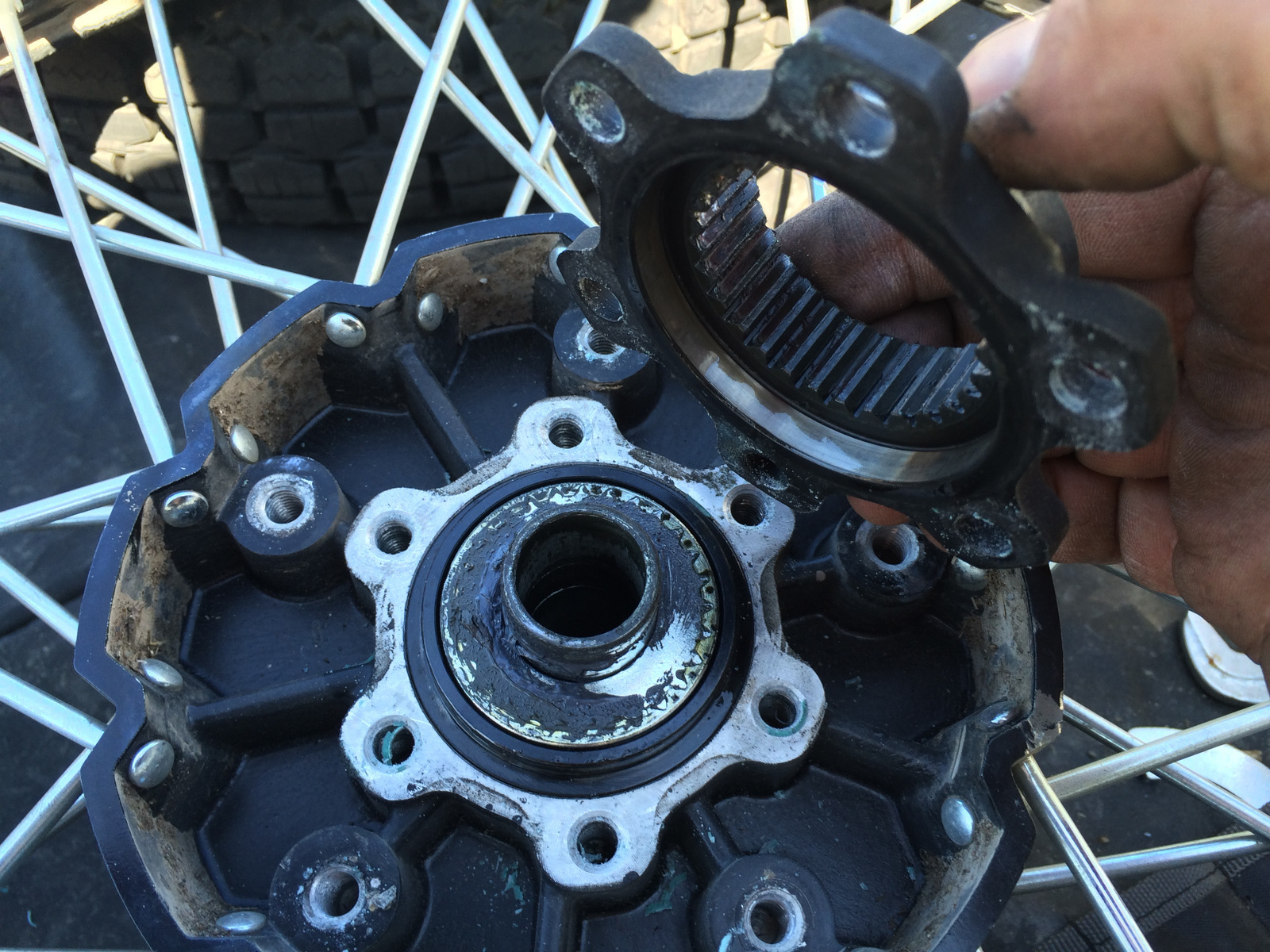
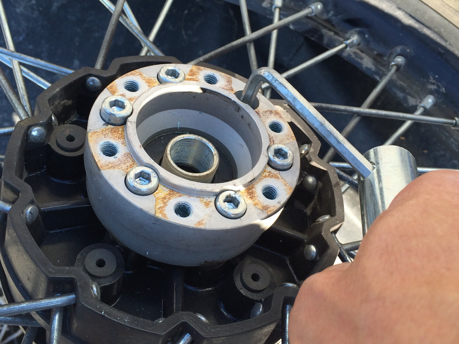
Step 12: Remove splined drive flange. First, remove the six (6) socket head cap screws retaining the splined drive flange to the spare wheel hub.
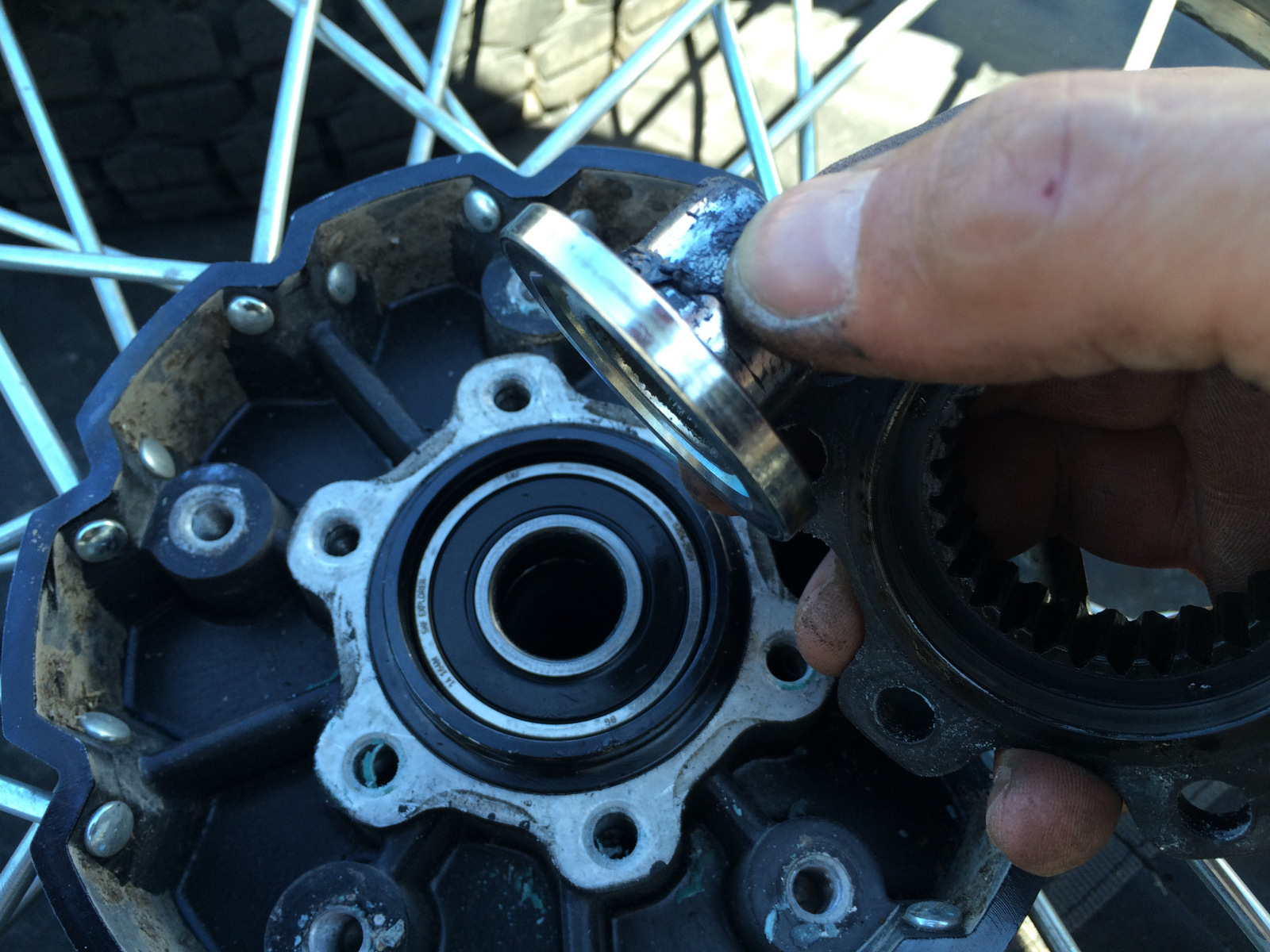
Step 13: Remove the splined flange, spacer and retaining ring.
Step 14: Install the right side front hub bearing retaining circlip previously removed in Step 5 in place over the bearing on the spare wheel hub.
Step 15: For safe keeping, install the splined flange, spacer and retaining ring removed from the spare wheel assembly onto the front hub.
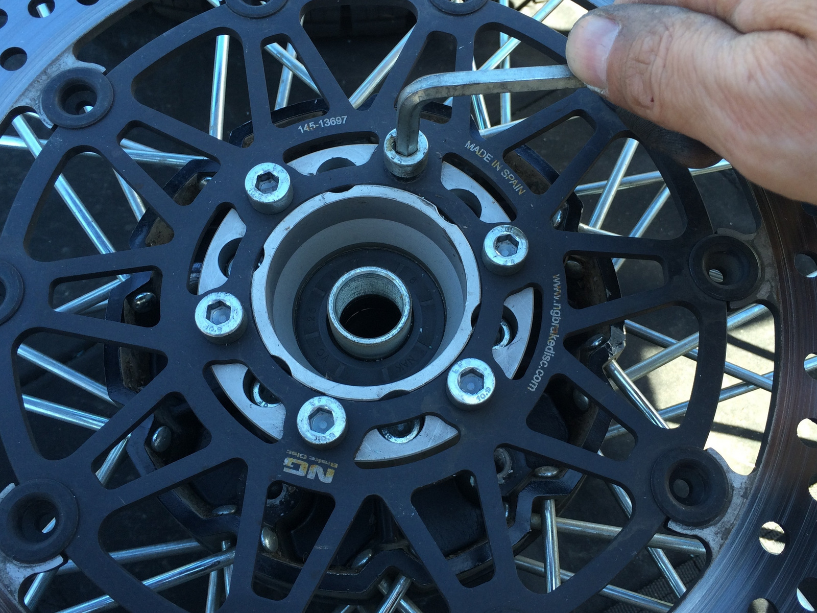
Step 16: Secure the front rotor spacer to the spare wheel hub with the six (6) socket head cap screws removed previously in Step 4 using a 6mm tool.
Step 17: Secure the front rotor to the front rotor spacer with the six (6) socket head cap screws removed previously in Step 4 using a 6mm tool.
Note: Mount the rotor and spacer where the splined drive flange was removed from the spare wheel hub in Step 6 opposite the spare wheel adaptor.
The spare wheel adaptor that is mounted on the wheel for use on the rear position DOES NOT need to be removed for the spare wheel assembly to function on the front position.
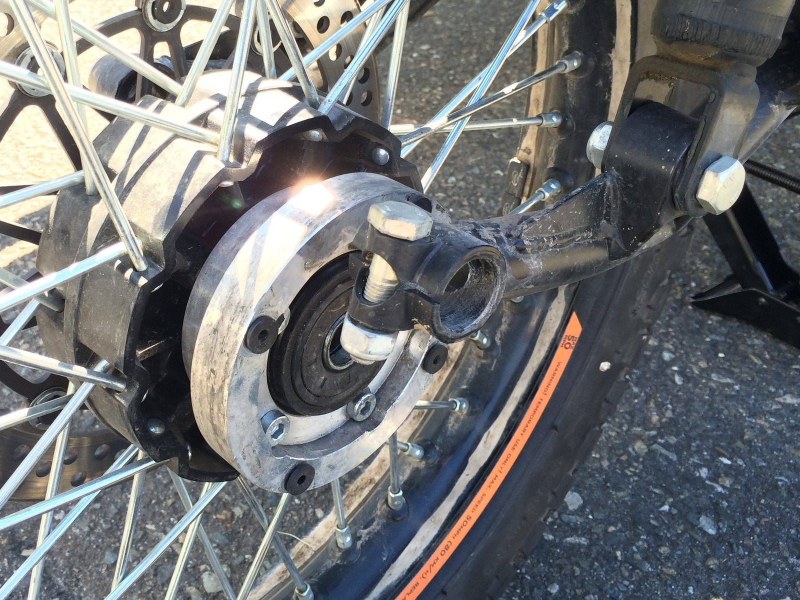
Step 18: Install the spare wheel assembly by lifting into place and partially insert the front axle from the left hand side.
Step 19: Having noted the position of the lower caliper bracket on the axle in Step 3, orientate in the lower caliper bracket in the proper position on the right side of the front hub and continue axle installation.
Step 20: Insert a suitable tool (screwdriver works well) into the hole on the left side of the axle and turn counterclockwise to tighten until it is fully seated.
Step 21: Secure the front axle pinch bolt on the left side of the front swing arm using two (2) 17mm tools.
Step 22: Re-install the front caliper back in position over the front rotor.
Step 23: Reinstall the two bolts securing the front brake caliper upper bracket to the lower caliper bracket with a 17mm tool.
Step 24: Confirm the front brake hose is routed properly and all hardware is securely fastened.
Step 25: Remove support used under the engines oil sump to suspend the front wheel assembly off the ground.
Step 26: Lower the motorcycle from the center stand by pushing forward on the handle bars and covering the front brake lever to prevent the motorcycle from rolling away.
Step 27: Set parking brake.
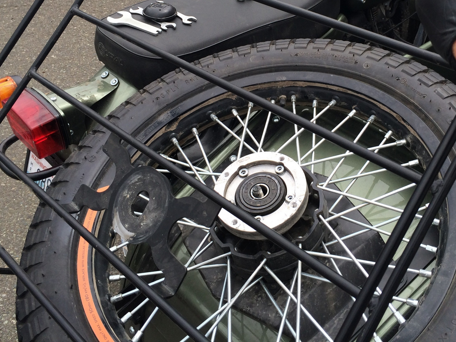
Step 28: Install the front wheel assembly onto the spare tire carrier.
Step 29: Secure the spare wheel retaining nut using the tool from your Ural tool kit (Part No. IMZ-8.128-24018).
Step 30: Almost done! Clean up tools and debris from the surrounding area and hit the road!